Note: Be no longer manufactures BeBoxes; this information is provided for reference purposes only. See our hardware strategy clarification for more information.
Below you'll find technical specifications for the BeBox Dual603. Configurations
of the BeBox vary in components (drive size and speed, RAM preinstalled,
etc.) - these specifications are applicable to all versions of the Dual603
model.
Contents
BeBox Processor Boards
The BeBox includes two printed circuit assemblies:
- A main processor Board for the two PowerPC 603/603e CPUs, DRAM, and
expansion slots
- An I/O board that contains most of the I/O connectors
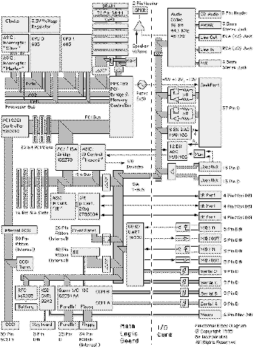
This diagram shows the major blocks of the BeBox system. The dotted line
shows the connector interface between the main processor board and the I/O
board. The diagram is arranged for display on smaller monitors.
BeBox Main Processor Board
The processor board is a 6-layer printed circuit board (PCB) with components
mounted only on the top surface. Integrated circuits and passives are surface-mounted,
connectors are through-hole. The processors are soldered directly to the
processor board.
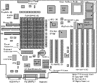
Diagram of the BeBox Main Processor Board
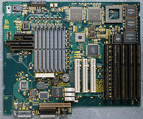
Photo of the BeBox Main Processor Board
Main Processor Board Components and Connectors
Qty  Component                                Connector
---  -------------------------------------    --------------
 2   PowerPC 603 or 603e RISC processors
     at 66 or 133 Mhz
 8   72-bit DRAM SIMM Sockets                 72-pin
 1   8-bit flash ROM
 3   32-bit PCI slots at 33 MHz               32-bit PCI
 5   16-bit ISA slots                         16-bit ISA
 1   Real-time clock with
     battery-backed-up NVRAM
 1   Internal SCSI port                       50-pin ribbon
 1   External SCSI port                       50-pin SCSI II
 1   Parallel port                            25-pin D-shell
 1   Internal ATA (IDE) port                  40-pin ribbon
 1   Keyboard port, PC/AT-type                5-pin DIN
 1   Internal floppy port                     34-pin ribbon
 1   Speaker port                             2-pin
 1   Front panel connector                    26-pin ribbon
 1   Power LED
 1   Disk-activity LED
 1   Interrupt switch
 1   Reset switch
 1   Bar-graph LED driver
BeBox I/O Board
The I/O board is a 4-layer PCB, approximately 4.25 x 7 inches. Components
are mounted on both sides of the board; I/O connectors are mounted perpendicular
to the plane of the board. The I/O board connects to the main processor
board through a single, gold-edge finger connector.
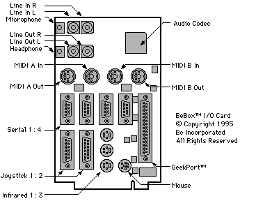
Diagram of the BeBox I/O Board
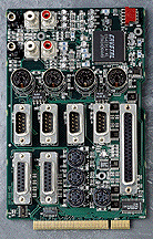
Photo of the BeBox I/O Board
I/O Board Components and Connectors
Qty  Component                                Connector
---  -------------------------------------    --------------
 1   "GeekPort"                               37-pin D-shell
 4   Advanced serial ports                    9-pin D-shell
 1   Mouse port, PS/2-type                    6-pin mini DIN
 2   Joystick ports                           15-pin D-shell
 2   MIDI out ports                           5-pin DIN
 2   MIDI in ports                            5-pin DIN
 3   Infrared (IR) I/O ports                  6-pin mini DIN
 1   Internal CD audio line-level input       5-pin strip
 1   Internal microphone audio input          4-pin strip
 1   Internal headphone audio output          4-pin strip
 2   Line-level input (L/R)                   RCA jacks
 2   Line-level output (L/R)                  RCA jacks
 1   Microphone input stereo phono jack       3.5 mm
 1   Headphone output stereo phono jack       3.5 mm
 1   16-bit stereo sound system
     @ 48 and 44.1 KHz
Processor Bus
The processors, PCI bridge/memory controller, interrupt controllers,
and logic analyzer probe connector are all on the processor bus. The bus
runs at 33 MHz, and includes a 64-bit data path with optional parity, a
32-bit address bus, and control signals. The processors and 105 are programmed
to operate in "big-endian" mode.
Processors
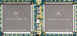
There are two PowerPC 603/603e processors on the BeBox main processor
board. The processors are soldered directly to the logic board; there is
no provision for processor sockets. The processors run internally at 66
or 133 Mhz.
Memory Controller and PCI
Bridge
The MPC105 chip performs the following functions:
- DRAM The memory controller supports up to 8 banks
of RAM in 4 socket pairs. RAM SIMMs must be added in pairs to make up the
64-bit data path. Parity is not checked in the initial release of the BeBox
software, but parity checking will be an option in future releases. Parity
SIMMs (36-bit) or nonparity SIMMs (32-bit) may be used. The RAM SIMMs should
be 60 nS or faster, fast page mode. SIMMs of 1, 2, 4, 8, 16, 32, and 128
MB size are supported.
- FLASH ROM The memory controller assembles bytes from
the flash ROM into 32-bit words for the processor. A single flash ROM of
128 K bytes is provided. The first sector of the ROM is write-protected
and contains code for updating or repair of the rest of the ROM from a
floppy disk.
- PCI Bridge The PCI bridge performs processor-to-PCI
and PCI-to-memory system transactions. Access to the memory system from
PCI are snooped by the processors to maintain cache coherency. Endian conversion
is performed for transactions between PCI and the processor bus.
- Processor Bus Arbitration The 105 provides arbitration
for the processor bus. Each processor and PCI may arbitrate for the bus.
PCI Bus
The PCI bus is provided for high-performance or high-bandwidth I/O devices,
such as SCSI and graphics adapters.
The PCI bus is shared by the MPC105, the SCSI controller, 3 32-bit 5-volt
slots, and the PCI-to-ISA bridge. All 3 PCI slots support bus masters. The
bus is clocked at the PCI-specified maximum speed of 33 MHz. All 3 slots
support full-length cards. While the slots are 5-volt slots, 3.3 V is also
supplied per the PCI specification.
ISA Bus
The ISA bus is provided for low-bandwidth I/O devices and for backwards
compatibility with such devices as network adaptors and modems. Cards added
to the ISA bus must have drivers compatible with the Be operating system.
ISA bus timing is generated by the Intel 82378 PCI-to-ISA bridge. The 82378
performs the following functions:
- ISA Bus Bridge The 82378 converts PCI accesses to
ISA accesses. Memory and I/O transactions are supported. The BeBox does
not use any ISA memory locations; ISA I/O addresses have been allocated
to the extra I/O features of the BeBox. A complete list of the usage of
the I/O space is available in the I/O address map (forthcoming).
The BeBox register addresses have been chosen to avoid standard ISA cards
such as modems and COM3 or COM4, LPT2 and 3, and FDD2.
- ISA Interrupts All standard ISA interrupts are routed
to the 8259 controllers, which are integrated into the 82378. PCI and SCSI
interrupts may be routed to standard ISA interrupts. The 8259s may be bypassed
by using the Be interrupt controller.
- ISA DMA The 82378 provides 7 scatter gather ISA DMA
channels. The channels are allocated as shown:
Channel 0 unused in BeBox
Channel 1 unused In BeBox
Channel 2 Floppy Disk Drive
Channel 3 Parallel Port
Channel 5 IDE
Channel 6 Audio Codec Capture
Channel 7 Audio Codec Playback
(Channel 4 is not available, it is used internally to cascade channels.)
NOTE: Development of hardware that makes use of the ISA
DMA features for the BeBox is discouraged. Developers should look to PCI
bus master cards for functions that would normally required DMA.
- PCI Bus Arbitration The 82378 provides a mastership
arbitration controller for the PCI Bus.
- I/O Decoding The 82378 provides signals used to create
I/O address decodes for the keyboard/mouse controller, real-time clock,
IDE, and the front-panel LED bargraph option.
I/O Devices
The following I/O devices are implemented in the BeBox.
SCSI
SCSI is provided by an NCR 53C810 SCSI controller on the PCI bus. The
53C810 controller provides fast/narrow SCSI II functionality. It is a bus
mastering controller, which can execute command scripts for scatter gather
operation.
The SCSI bus is connected to both a 50-pin internal connector and an external
50 Pin SCSI-2 Connector. Switchable SCSI terminators are provided at the
external connector. The Terminators will be disabled when a SCSI cable
is connected to the system. Additional information on SCSI hardware configuration
may be found in the [Be SCSI HW Guide].
Keyboard and Mouse Controller
Connections to the keyboard and mouse are through a PC-standard 8042
controller with standard PC BIOS. Connection to a keyboard is through a
standard 5-pin 180-degree female shielded DIN connector. Connection to
a PS/2-style mouse is through a 6-pin female mini DIN connector, which
is located on the I/O Card.
The BeBox does not come with a keyboard or mouse, allowing customers to
purchase the industry-standard models they prefer.
Floppy Disk Drive
Industry standard 3-1/2" MFM floppy drives are supported, at 720
K and 1.44 M. The floppy interface is through a 34-pin ribbon connector.
Power for the floppy drive is through a separate power harness to the power
supply.
Serial Ports
Four industry-standard, 9-pin, AT-style serial ports ports are provided.
The serial UARTs are compatible with the 16550 (16-byte FIFO) serial controller.
Two of the ports (Serial 1 and 2) are ISA/PREP-compliant, located in the
address space for COM1 and COM2. The other two ports (Serial 3 and 4) are
clocked by a nonstandard frequency compatible with MIDI. (Normal baud rates
will continue to be supported on these ports.)
Parallel Port
The parallel port is bidirectional and implements standard parallel
protocols. The external connector is an AT-standard 25-pin female D-shell
connector. Connection to the DMA channel and interrupts can be configured
through the device providing the parallel port function.
MIDI Ports
2 MIDI ports are supported. Each MIDI channel has its own FIFO UART.
5-pin DIN MIDI connectors are provided for in and out on each channel.
Standard MIDI drive is provided on the out connectors, and a standard opto-isolator
is provided for the input. No adaptors are required to connect the BeBox
to MIDI devices.
Joystick Ports
Two joystick game ports are provided, compatible with PC-standard game
controllers. The x-y data is sampled by an A/D converter to provide superior
resolution over standard joystick ports.
The connectors are standard 15-pin female D-shell type. No adaptors are
required to connect industry-standard joysticks to the BeBox. Each of the
connectors samples all 4 analog and 4 switch connections, allowing the
use of 4 simple joysticks with the addition of a splitter cable.
Real-Time Clock
A PC-compatible Real-Time Clock is provided.
Parameter RAM
144 bytes of nonvolatile RAM is provided. This RAM is located in the
real-time clock, and is dedicated to use by the Be operating system.
Battery
A replaceable 3 V coin battery (type CR2025) is provided for the real-time
clock.
Sound System
A 16-bit stereo CODEC is provided to sample and play sounds. Sample
Rates of 44.1 and 48 KHz and divisors are supported.
- Line Input Compatible with the 2 V P-P levels standardized
by CD audio players. Input Z > 4.7 KOhms. The connectors are two (L/R)
RCA-type jacks. Ground loop subtraction is implemented.
- Microphone Input Compatible with low-level dynamic
microphones. The connector is a 3.5 mm minijack.
- CD Audio Input Compatible with the 2 V P-P levels
from CD-ROM units. Connector is a 5-pin header with retainer, compatible
with the MV ProAudioSpectrum / Studio 16. Ground loop subtraction is implemented.
CD audio cables compatible with all major brands of CD drives are readily
available.
- Headphone Output Compatible with standard 30 Ohm "walkman"-type
headphones. The connector is a 3.5 mm minijack.
- Speaker Amplifier A medium-power amplifier drives
the internal computer speaker. A separate gain control is provided to adjust
the volume of the speaker.
- Line Output Compatible with the 2 V P-P levels standardized
by CD audio players. The connectors are RCA jacks. Ground loop subtraction
is implemented.
Infrared Ports
3 infrared (IR) ports are provided. Each port may be connected to an
IR receiver and an IR transducer. The ports may be programmed to perform
the functions of a learning remote control, or may be used to detect commands
for the control of the BeBox.
GeekPort
The "GeekPort" is a new feature connector unique to the BeBox.
It provides digital and analog I/O and D.C. power through a 37-pin connector
at the back of the chassis. This port is aimed at experimenters and small
entrepreneurs so that they may bring unique functions to the BeBox. The
GeekPort is located on the ISA bus and can be accessed by the CPU, a PCI
busmaster card, or an ISA busmaster card.
The GeekPort has the following features:
- 2 Bidirectional Data Ports Each 8-bit port may be
independently configured as input only, or output with readback. This allows
the user to configure the GeekPort as 16 inputs, 8 inputs and 8 outputs,
or 16 outputs. The data ports are protected against shorts to power or
ground.
- 4 A/D Pins Each of the 4 pins can be routed to a high-quality
12-bit A/D converter. An analog signal ground reference pin is provided.
The data A/D pins are protected against shorts to power or ground.
- 4 D/A Pins Each D/A pin is connected to an independent
8-bit D/A converter. An analog signal ground reference pin is provided.
The data D/A pins are protected against shorts to power or ground.
- 11 Power and Grounds 2 pins at +5 V, and 1 pin each
of +12 V and -12 V are provided. The power pins are protected by fuses
on the main processor board. 7 ground pins are provided. The shell of the
connector is connected to chassis ground for shielding.
- GeekPort Connector A 37-pin female D-shell connector
was selected to best meet the requirements of experimenters, due to the
following features:
- High Pin Count 37 Pins allows for plenty of signal
pins and adequate power and grounds.
- Readily Available The connector is listed in most
electronics catalogs, and is available in most shops that cater to the
experimenter.
- Mechanically Robust The shell of the connector is
rugged, and the pin spacing is large enough for inexperienced assemblers
to solder connections to the pins. The large size of the connector will
allow many types of devices to be built onto the connector itself or onto
a small PCB directly connected to the connector, or within a standard backshell.
- Not Standard on PCs This connector is not commonly
used on PCs so the risk of plugging an incompatible device into the connector
is greatly reduced. Even if a user accidentally attempts to connect a smaller
connector, the large size of the GeekPort connector prevents more than
a few pins near the end from making contact. The power connections have
specifically been grouped to the center of the connector to help prevent
the accidental shorting between the power pins of the GeekPort to external
cables and devices.
Support Functions
3.3 V Voltage Regulation
3.3 V is regulated down from the 5 V supply.
Reset and Interrupts
Reset and interrupts are supported via two FPGAs. These chips perform
the following functions:
- Reset Counter Provides reset pulse to the processors.
- Bus interface Connects CPU bus to interrupt registers,
supports split transaction bus.
- Interrupts - Inter-processor Provides communication
between processors
- Interrupts - I/O Each processor has a interrupt mask
register to permit each of the interrupts to be individually masked to
each processor.
Reset and interrupt are available as front panel switches. The left and
right switches work in combination to provide the following functions:
Left  Right  Function
----  -----  -------------------------------------------------
 N     N     Normal operating condition
 Y     N     Interrupt pressed, system interrupts to debugger
 N     Y     Reset pressed, no effect (safe to press either button)
 Y     Y     System hard reset. Contents of RAM will be lost.
Clock Generation
A PLL is used to generate all system clocks from a 14.31818 MHz crystal.
A second 32 KHz crystal is provided for the real-time clock.
Product specifications are subject to change without notice. | 


